In-situ testing in Omaha provides direct evaluation of subsurface conditions without the disturbance caused by sampling and transport to a lab. The region’s variable geology—ranging from Missouri River alluvium and loess-mantled uplands to weathered Pennsylvanian shale and limestone—demands reliable field methods to confirm design assumptions. A fundamental verification tool is the field density test (sand cone method), which measures in-place soil compaction against specifications tied to ASTM D1556 and local building codes for engineered fill and backfill.
These investigations are essential for commercial pad sites, roadway embankments, utility trench backfill, and stormwater detention basins across Douglas and Sarpy counties. Testing is routinely integrated with geotechnical drilling and laboratory strength profiling to validate bearing capacity and settlement predictions. By pairing nuclear-free density verification with supplementary strength and moisture assessments, project teams achieve code-compliant compaction and long-term foundation performance under Nebraska’s freeze-thaw and wet-dry cycles.
In Omaha's loess, a passive anchor's capacity isn't just about dead weight; it's about the intact shear strength of the undisturbed soil block beyond the failure wedge.
Methodology and scope
Local considerations
A hydraulic rotary drill rig, equipped with an overburden casing advancer, is the first piece of equipment mobilized when verifying conditions for an anchor installation in East Omaha. The crew drills through the fill and alluvium to seat the casing into the underlying bedrock or dense till. Skipping this casing step in loose sand can trigger a borehole collapse that undermines adjacent sidewalks or utilities. Once the hole is open, a single-bore multiple anchor system may be deployed if the soil profile indicates a deep-seated failure surface. The installation concludes with a staged stressing operation, where a calibrated hydraulic jack applies load increments while a dial gauge monitors tendon elongation. Any deviation from the predicted elastic stretch curve prompts an immediate halt to evaluate whether the bond zone has been compromised by a hidden cavity or a lens of organic silt.
Applicable standards
FHWA-NHI-05-037 (Ground Anchors and Anchored Systems), PTI DC35.1-14 (Recommendations for Prestressed Rock and Soil Anchors), ASTM A416/A416M-18 (Standard Specification for Low-Relaxation, Seven-Wire Steel Strand for Prestressed Concrete)
Associated technical services
Active Tieback Design and Stressing Protocol
Full design of high-capacity strand anchors with sacrificial corrosion protection, including lock-off load calculations and step-by-step stressing procedures coordinated with excavation lifts.
Passive Deadman and Soil Anchor Systems
Geometric design of concrete deadmen or grouted passive anchors in granular riverine soils, verifying the passive pressure wedge does not overlap with adjacent footings or utility corridors.
Proof and Performance Testing Oversight
On-site supervision of anchor testing per ASTM A416 and PTI standards, logging creep rates and elastic versus plastic movement to validate the ultimate bond capacity assumed in the design model.
Wall Drainage and Anchor Head Protection
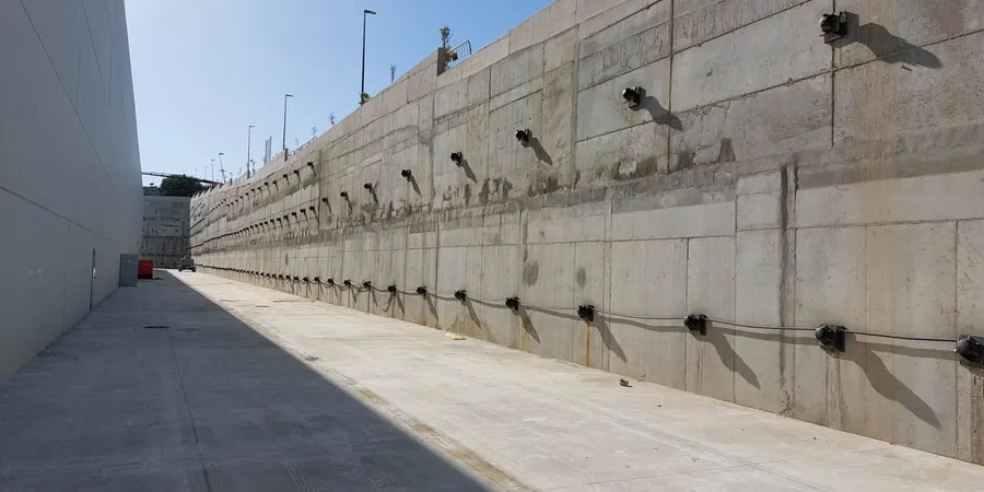
Detailing of waterproofing at the anchor head penetration through the wall, and specification of subsurface drainage paths to prevent hydrostatic pressure buildup behind a fully restrained anchored system.
Typical parameters
Frequently asked questions
What distinguishes an active anchor from a passive one in a retaining wall application?
An active anchor is stressed and locked off after the wall achieves sufficient strength, actively compressing the soil mass and minimizing lateral deflection. A passive anchor, like a deadman block, only engages its full resistance as the wall begins to move and pull against it. The choice in Omaha depends on allowable movement: active systems are preferred near sensitive structures in Midtown, while passive systems can be more economical for isolated bridge abutments.
Can an anchored wall be designed for the loess soils common in western Omaha?
Yes, but it requires careful attention to saturation-induced collapse. The design bond zone must be located below the maximum depth of seasonal wetting, and the unbonded length must be greased and sheathed through the upper loess layer. We specify a higher factor of safety on the tendon load and often recommend pre-grouting the borehole to seal any macropores before placing the tendon assembly.
What is the typical cost range for designing an anchored excavation support system in Omaha?
For a typical single-tier active anchor system on a residential or light commercial excavation, the engineering design and load-testing specification typically ranges from US$950 to US$3,420, depending on the number of anchor rows and the complexity of the subsurface profile encountered during the site investigation.
How long does an anchor installation and stressing operation take on a typical site?
For a crew installing 4 to 6 active strand anchors with a depth of 30 to 40 feet, the drilling, tendon placement, grouting, and initial stressing can be completed in 2 to 3 days. A 7-day waiting period follows for grout strength gain before final lock-off. In Omaha's dense shale, drilling rates slow considerably, which can extend the schedule by a day compared to sites with softer loess.