I was out near the Missouri River bluffs last month, looking at a site for a new medical office building. The geotechnical borings showed solid limestone at 30 feet on one side of the lot, but the driller lost refusal at 55 feet just eighty feet away. That kind of erratic bedrock surface is classic for Omaha’s glaciated terrain and Pennsylvanian bedrock. We ran a refraction line across the property, and the tomogram showed a buried paleochannel cutting right through the middle of the pad. Without that image, the structural engineer would have designed for uniform bearing conditions that simply weren' t there. Seismic tomography gives you a continuous subsurface velocity model, not just point data. When we pair it with SPT drilling at key locations, we can tie the geophysical boundaries to actual N-values and soil descriptions, making the ground model defensible for the Omaha building department.
Seismic tomography replaces guesswork between boreholes with a continuous velocity cross-section you can hand to your structural engineer.
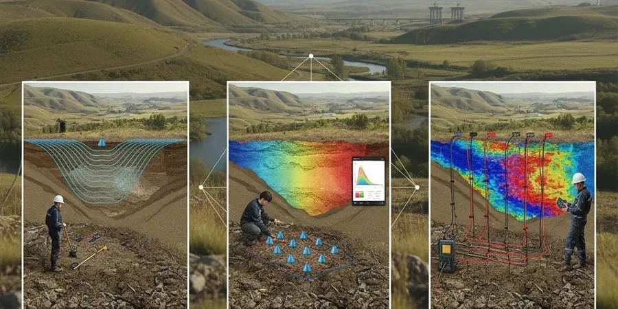
Methodology and scope
Local considerations
Omaha winters mess with seismic surveys in ways that don't show up in the textbooks. When the top six inches of ground freezes solid, you get a high-velocity surface layer that masks the real stratigraphy underneath. We've seen apparent bedrock at three feet on a February refraction line that turned out to be frozen silt sitting on 25 feet of soft alluvium. The Missouri River valley also has a nasty habit of hiding abandoned channel deposits: loose saturated sands that a standard boring might miss if the split spoon happens to hit a gravel lens. A reflection survey can pick up the base of those paleochannels, and when we process the S-wave data we can flag intervals where the VS drops below 500 ft/s—exactly the kind of soft zone that triggers a site class E or F designation under ASCE 7. In eastern Nebraska, missing that means your whole lateral design could be off by a full seismic design category.
Applicable standards
ASCE 7-22 – Minimum Design Loads, Chapter 20: Site Classification Procedure, IBC 2021 Section 1613 – Earthquake Loads and Site Ground Motion, ASTM D5777-18 – Standard Guide for Seismic Refraction Method, ASTM D7128-18 – Standard Guide for Seismic Reflection Method, NEHRP Recommended Provisions – VS30 averaging and site class boundaries
Associated technical services
P-wave refraction tomography
Standard first-arrival refraction using vertical geophones. Best for mapping bedrock depth, rippability, and detecting lateral velocity contrasts in the upper 100 feet.
S-wave (MASW-style) crosshole or downhole
We run active-source S-wave profiles to measure shear-wave velocity directly. The VS30 value we compute goes straight into your structural drawings for seismic base shear calculations.
High-resolution reflection profiling
For deeper targets like fault mapping or basin geometry beneath the glacial till, we use CMP reflection methods with 48-channel spreads and longer offsets.
Site class determination report
A stamped deliverable with the VS30 calculation, NEHRP site class letter, and seismic design parameters per ASCE 7 Table 20.3-1, ready for the building permit package.
Typical parameters
Frequently asked questions
How deep can seismic refraction see at a typical Omaha site?
With a standard 240-foot spread and a sledgehammer source, we typically image to 60–80 feet below grade in the loess and till soils common around Omaha. If you need to reach deeper—say 150 feet to map bedrock beneath the Missouri River alluvium—we extend the spread length and switch to a weight-drop source. Reflection surveys can go much deeper, 300 to 500 feet, which is useful for regional fault studies.
What does a seismic tomography survey cost in the Omaha metro?
Most projects in the Omaha area fall between US$2,550 and US$5,600, depending on the number of lines, spread length, and whether we run both P-wave and S-wave profiles. A single refraction line for a residential lot is on the lower end; a multi-line commercial survey with reflection processing and a full site class report lands closer to the upper end.
Do you need to drill boreholes if you already have seismic data?
Seismic gives you velocity, not soil type. A velocity of 3,000 ft/s could be dense till or weathered shale. We always recommend at least one calibration boring so we can anchor the tomogram to real material descriptions and N-values. The combination of continuous geophysics plus targeted borings is what gives you a defensible ground model for the city review.
How long does the fieldwork and reporting take?
Field acquisition for a typical two-line survey takes one day on site. Processing and interpretation runs three to five business days after that. If you need a rushed report for a permit deadline, we can turn the final site class determination in 48 hours—just let us know when you schedule.